Morphological features of magnetorheological elastomer degradation under a natural weathering environment
Morphology of unexposed samples
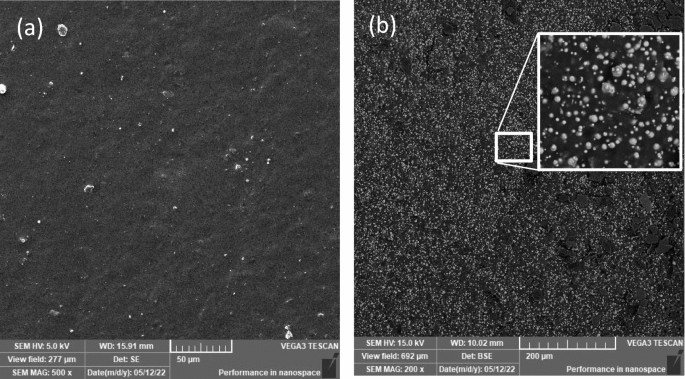
The sample was verified for flaws during production and sample preparation before being exposed to weathering conditions. At the same time, the original state was recorded for comparison with the exposed samples. Figure 1 shows a surface and cross-section SEM micrograph of the MRE sample, which is used as a qualitative reference and for comparison with the exposed sample. The original samples are discovered to have uniform flat surfaces, as shown in Fig. 1a, and similar longitudinal section surfaces, as shown in Fig. 1b. The CIPs in the MRE were spread uniformly and isometrically. There were indications of voids and aggregation within the CIP, although only in a modest proportion.
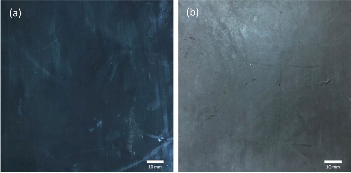
Another sign of a good reference before exposure is a bright and sharp coloration without being pale or fading. The MRE sample used in this study was a uniform dark blackish color. The discoloration is a defect that occurs as a result of prolonged exposure to UV radiation and is a sign of surface degradation. This is typically linked to photooxidation because the development of color occurs concurrently with other signs of photooxidation in the overall aging process1. As a result, as illustrated in Fig. 2, any defect caused by discoloration can be easily identified and detected. As shown in Fig. 2a, as the exposure time increased, the surface of the MRE sample faded from bright black to dull gray. This is an early indication of surface discoloration caused by MRE surface degradation. However, scientific evidence and evaluation of the fault, as well as a few other degradation elements, will be necessary to offer records and patterns of the defect’s deterioration process. The condition of the unexposed surface is extremely important because it depicts the original source when evaluating changes in the surface morphology of the MRE. It is understood that the process of MRE degradation under weathering influence begins only with the surface exterior.
Observations during exposure
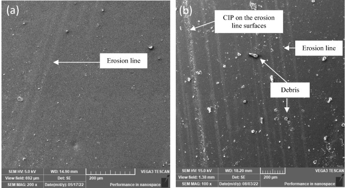
The hypothesis that the MRE sample gradually degraded after prolonged exposure of 30 days to natural weathering was confirmed15. In the current study, samples were further exposed to a natural tropical climate for up to 90 days. Initial visual inspection revealed that the MRE experienced discernible discoloration during the weathering process up to 90 days, which was not evident at 30 days. As the exposure time increased, the sample surface became increasingly fuzzier. Long-term UV radiation and rainwater flow are believed to contribute to degradation with discoloration effects. The change, however, occurred on the sample’s surface and was imperceptible, which needed further scientific investigation. Therefore, detailed observation under SEM revealed more evidence of the changes. Figure 3a depicts the surface of the MRE after 30 days of exposure15, with the degradation process advancing to the state depicted in Fig. 3b at 90 days. At this point, the number of apparent erosion lines on the sample has expanded and grown in breadth size, with significant thickness. It is worth noting that there was clear evidence of contaminants and debris presumed to have come from both dry (wind) and wet (rainwater) environments. Some constituents of rainwater are of local origin, while others have been transported by winds from elsewhere. Mineral and organic dust are precipitated by rainwater.
SEM image of surfaces for MRE (a) after 30 days15 and (b) after 90 days of natural weathering exposure.
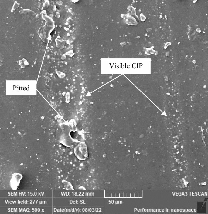
Contaminations in the environment that have an adverse effect on the MRE surface were induced by winds and rainwater. Rainwater contains dissolved gases that affect pH values of approximately 5.5 or lower, whereas the presence of chlorides in rainwater exacerbates the quality of erosion properties. Simultaneously, the repeating process of tropical climate involving these two parameters has aided in the precipitation of the degradation process. As the exposure time increases, the erosion line expands, and pits appear more prominently on the sample surface. During the day, UV radiation from the sun strikes the surface of the MRE, forming a thin layer on the surface that is chemically modified. Following that, rainwater leached away soluble degradation stuff during the rainy day, exposing a fresh layer that could be attacked by UV radiation once more. This repeating process has previously been observed by18 in different materials that experienced similar conditions. Erosion lines allowed air and rainwater to enter the matrix, causing oxidative degradation of the MRE matrix molecules. The action is suspected to be caused primarily by trapped water on the deteriorated matrix surfaces, which accelerates the process known as the photooxidation reaction and is aided by water molecules of OH− and H+ ions. These ions primarily reflect the degree of degradation at various dominance levels. The higher the concentration of H+ ions in the solution is, the more acidic the solution becomes, and the solution becomes more basic as the concentration of OH− ions increases. Consequently, water has a unique property that causes it to behave as an acid or a base depending on the concentration of these ions, influencing the degradation of the MRE surface. In the case of natural weathering, the process occurred naturally and solely as a result of the climate pattern. After 90 days in a tropical climate, the repeating process exposed the CIPs and pitted them, which was visible on the MRE surface, as shown in Fig. 4.
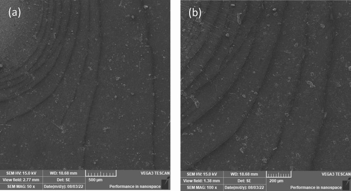
The weathering effect on the MRE surface has been observed primarily as a result of matrix surface degradation. Furthermore, the pitted surface caused sufficient UV light scattering on the matrix surface, and after prolonged exposure to weathering conditions such as oxygen, sunlight (UV), or ozone, random cracks appeared on the surface. The material was exposed to a natural tropical climate with modest degradation, and microcracking was most likely caused by the ozone effect via chain scissions and photooxidation reactions, particularly during high humidity conditions. Further morphological investigation revealed that some surfaces had surface microcracking and a few effects rarely reported on MRE, such as ripple and the so-called elephant skin effect. Because the MRE was exposed to natural weathering conditions for an extended period of time, the ripple effect or capillary-like wave pattern observed in this study was believed to be caused by the environment’s constant back-and-forth movement of rainwater, aided by wind blowing over the surface. When the process was repeated for a longer period, especially in hot daytime conditions, the dried surface shrank, and surface tension or surface energy was created on that affected surface. Essentially, the equivalent attractive force existed between the molecules on the surface of the MRE matrix substance. As a result of the dominant surface tension, surface cracking formed, with the pattern exactly following the curvy of the ripple. Due to the sample’s hanging position outside, surface tension, gravity, rainfall inertia, and the sample’s placement all impacted the ripples, as seen in Fig. 5a, and a closer image is displayed at a higher magnification rate in Fig. 5b.
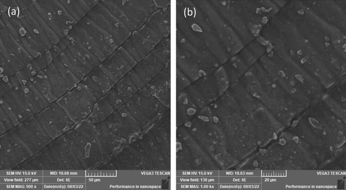
The microcracking contour began as a smaller curved line on the affected surface and progressed over time into larger curved lines with an ovulate curve pattern. The distance between each microcracking curvy widened as it moved away from the locus point where it originated. It appears that as the ripples progressed, the surface tension or surface energy weakened, slowing down the microcracking process, and as a result, the area of the region bounded by the two curves expanded. The microcracking contour on that designated area indirectly ages the MRE sample and aids in the degradation process. A closer look at the surface near the source of the contour revealed that a crinkle pattern had formed within the ripple area. During daylight exposure, particularly in less rainy conditions, drying shrinkage characteristics were observed as a result of the natural demand for rainwater as a plasticizer, which resulted in the formation of the elephant skin effect, as shown in Fig. 6. Observations revealed that the elephant skin effect can be triggered by any drying condition that does not result in water vapor condensation on the fresh surface34. There is always a condition in tropical climates where sunlight hits longer before raining. In this study, there was a period of less rain and higher temperatures between the 30th and 70th days of exposure, and it was suspected that these climatic conditions influenced the formation of the elephant skin effect. A low relative humidity was also recorded during the same time period, and this condition agreed with another study34 in which the elephant skin effect was observed in a drying environment with low relative humidity.
The rapid drying of MRE matrix exposed surfaces via moisture evaporation and self-desiccation accelerated the formation of the elephant skin effect. Figure 6a clearly shows the elephant skin effect, while Fig. 6b demonstrates a closer image displayed at a greater magnification rate. The formation was generated by the affected skin being pulled out, resulting in wrinkles, which were also indicative of the viscoelastic behavior of the MRE that has both elastic and viscous characteristics. The viscous component that exceeded the elastic limit remained wrinkled, while the nonwrinkled segment was elastic. As a consequence, the exposed surfaces of the MRE matrix developed a rough texture and occasional cracks. Contamination from dirt and dust is one of the most evident surface conditions visible in Fig. 6. Those images are thought to be trapped by the waxy residue used as a mold release agent. The wax’s thin oily surface layer provided a foundation for dirt and dusting powders to adhere to. The stain on the surface may also be related to MRE discoloration after prolonged exposure to the environment. Further microstructural investigation was carried out to determine the mechanisms that resulted in the formation of the aforementioned defects and further degraded the MRE due to natural weathering. As a matter of consistency, it was assumed that the distribution of UV radiation, ozone, and rainwater ions was uniform across the entire MRE sample surface and felt on a flat plane. However, the defective areas observed during the study period were localized and originated from and depended on the initial conditions following the fabrication process. As a result, UV radiation, ozone, and rainwater ions have little effect on the majority of the exposed surface. Furthermore, the wind blow influenced the localized affected area, bringing all the contaminants and thus accelerating the degradation process.
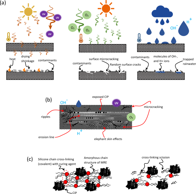
In general, the degradation process and physical changes in MRE exposed to natural weathering are highly dependent on a particular time period, so in a brief amount of time, the condition will not change permanently. MRE, on the other hand, will gradually undergo permanent changes in accordance with or directly proportional to the duration it endures for an extended period of time at an elevated factor such as temperature, humidity, wind speed and rain. As a result of the evidence gathered in this research, irreversible chemical processes occurred, implying that the MRE degraded. This undesirable progress can be simplified as illustrated in Fig. 7. Figure 7a depicts a cross-sectional representation of the reactions that occurred as a result of the influence of time, temperature, humidity, UV, ozone, and rainwater ions on the deterioration of MRE characteristics. The summation of different effects on the surface of MRE can therefore be interpreted as shown in Fig. 7b. As previously stated, the main contributor to the cracking of the MRE surface was related to cross-linkage scission caused by ozone impacts, as seen in Fig. 7c. The understanding of this process has spurred more inquiry since it is needed to comprehend the characteristic changes at a larger scale, such as mechanical properties.
Simplified scheme of (a) cross-sectional view of the UV, ozone, and rainwater ion reactions and their effects on the MRE surface, (b) top-view of the typical 90-day effects of weathering on the MRE surface in a tropical environment, and (c) schematic illustration of the scission of cross-links in the MRE matrix’s molecular chain structure.
Observation of mechanical properties
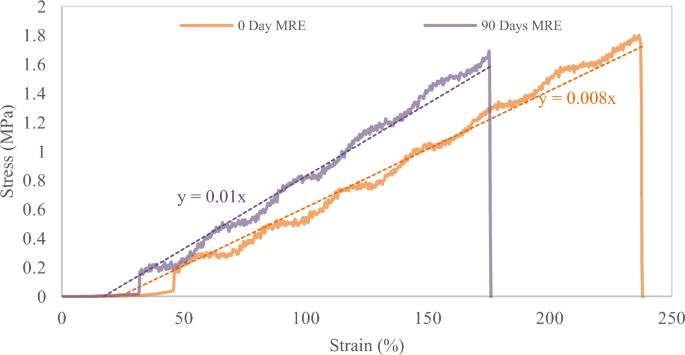
The micrography study showed the microlevel failure that caused the MRE to degrade. It was assumed that those failures had an impact on the MRE properties as a result of the reaction process described in the preceding section. For instance, it is believed that chain scission reactions reduce the crosslink density and consequently cause the creation of more or longer dangling chain ends, softening and losing their elastic properties. On the other hand, age-related crosslinking can cause the substance to become more brittle and stiffer. The evaluation under stress and strain relation indicates that the sample after 90 days exhibits those conditions and is plotted as shown in Fig. 8. The overall pattern clearly shows that increasing the slope of the graph represents growing stiffness. The breaking point was much sooner than in the sample that had not been exposed to natural weathering, confirming the hypothesis about elasticity loss. The tensile test results also indicate that the exposed sample has a 41% difference in elastic modulus, with a 52% increase over the sample that has not been exposed to natural weathering, as depicted in Fig. 9a.
Figure 9b depicts the variance in sample elongation at break. After 90 days, the elongation at break of the exposed sample showed a clear decrease. The value was determined with a difference of at least 30% and a decrement of 26% in comparison to the unexposed sample. The degradation could be ascribed to the severity of chain scission during the 90 days of exposure with the presence of typical UV, ozone and tropical climate changes. These mechanical property vicissitudes can then be translated into variations in failure at the microstructural level, as observed under electron microscopy. The use of scientific methods and techniques in the study has demonstrated great attention to detail and a very precise failure pattern in relation to changes in the sample mechanical properties caused by the natural weathering degradation process. The image obtained showed that MRE was metamorphosed by the aging factor naturally from the tropical climate in 90 days, which has rarely been reported for MRE elsewhere. Interestingly, all of the images were particularly for tensile failure and were only compared for the sample before and after exposure.
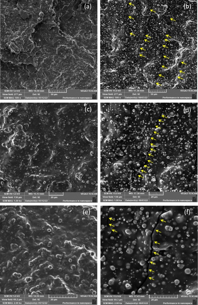
Even though all samples have the same matrix and particle ratio, due to exposure to natural weather for a period of time, tensile failure exhibits distinct characteristics and behavior. SEM observation reveals significantly less evidence of CIP protrusion in the unexposed sample of Fig. 10a. However, even under moderate magnification, it is clear from Fig. 10b that the exposed sample displays typical brittle failure on the matrix as well as more CIP protruding on the surfaces. Furthermore, referring to the area under the stress‒strain curve in Fig. 8, which depicts energy, reveals that the brittle failure of the exposed sample expends much less energy than the ductile failure of the unexposed sample. Ductile failure of unexposed samples occurred at higher strain and proceeded slowly, with deformation of the rubber occurring along the way, whereas brittle failure of exposed samples occurred at a much lower strain. The development of microcracks or hairline cracks on the surface was the primary distinction between the failures. In terms of brittle failure, localized residual stresses caused cracks to develop and spread more quickly in brittle media than in slightly ductile media, where the stress dispersion was delayed.
Given that UV exposure only affects the surface of the MRE matrix that is exposed to direct sunlight, UV irradiation significantly reduced the elongation at break and tensile strength of the exposed MRE and increased its stiffness. It consequently turned hard and fragile. In comparison, the SEM image of the unexposed sample at higher magnification in Fig. 10c does not appear to have any surface cracking, and the CIPs were also shown to have less bulging on the surface. While Fig. 10d depicts the surface condition, there is a crack line across the surface, as indicated by the arrows, and the surface was formed with CIP, which is clearly visible. This could be due to the firm contact with the matrix, whereas the exposed sample could have a weaker contact with the matrix, resulting in more protruded CIPs on the surface after tensile failure. Further investigation at higher magnification reveals that the crack in Fig. 10e for the unexposed MRE remains invisible; however, further cracks were observed in Fig. 10f for the MRE exposed for 90 days, indirectly justifying the hypothesis and previous findings.
Topography evaluation by AFM
The determination of MRE surface characteristics before and after exposure was analyzed using AFM, an essential method for characterizing defected surfaces in a more localized area. The AFM contact mode method was used in this study to identify surface topography and reliably identify the differences between the conditions before and after 90 days of exposure. The AFM assessment established the durability performance of the MRE sample under natural weathering influences and its correlation with mechanical and microstructural characteristics. AFM topography evaluation of the MRE surface is thought to significantly influence and reflect the bulk properties of the MRE itself. Despite the fact that the surface scanned was localized and nanoscale in nature, the data impact of that specific area was macroscopically significant.
AFM, unlike most other surface analytical methods, can investigate the topography of MRE samples down to the lowest scale under controlled conditions. Figure 11 depicts AFM images of both unexposed (Fig. 11a) and 90-day exposed (Fig. 11b) MRE samples subjected to natural weathering using contact mode. The scan size was 10 × 10 µm2, and the height range was 400 nm from the white to the black of the scale bar. Given that scan size has a major impact on the scaling results of AFM measurements, visual examination showed that using a large scan size (10 × 10 µm2) captured reasonably good images in this study. The horizontal line scan in Fig. 11c for both the unexposed (red) and exposed (green) samples indicates the height range that represents the surface condition after its reaction to natural weathering. The green line in Fig. 11c of the exposed MRE sample plainly shows a deeper value in the height range, while it is shallow for the original sample without any exposure. During natural weathering, the presence of continuous ozone concertation has higher oxidative capabilities and is noteworthy to become more aggressive at low humidity, in which ozone leads to aggressive cross-linking reactions enabling deeper cavities.
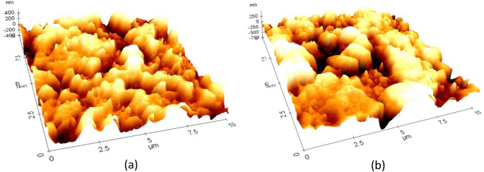
Chain scission has been observed under high humidity conditions, which results in more shallow cavities on the matrix surface. As a consequence, after 90 days of contact, the MRE sample developed cavities on the matrix surface that were much deeper than those that existed immediately after fabrication, also known as the unexposed sample. A tropical climate with a tolerable humidity percentage and constant ozone encourages cavity development. Accordingly, cavity characteristics were observed with the assistance of AFM measurements and analysis. Figure 12 depicts in greater detail the distinctive and exceptional configuration of the degraded surface of MRE caused by natural weathering. One of the peculiar features of surface degradation can be determined by the wider formation of a deep area on the MRE surface under nanoscale height range 3D projection, as shown in Fig. 12b. The cavities were consistent and optimally formed throughout the test exposure; however, in this area, the localization of the cavity was not consistent and contributed to the depth uncertainty, encouraging a similar level of uncertainty in the cavity shape. The localization of the cavity becomes evident as the exposure duration increases, resulting in the observation of a wider and deeper cavity.
Tags: environment

